
Step 1. Modify the Plastic NEMA Box
You’ll need:
- Box
- Drill, 5/8″ hole saw
- 11/16″ hole saw
- Pen
- Ruler
- Deburr tool
Steps:
- Mark the centers of each hole using the ruler and pen per Figure 1 (hole locations within 1/8th inch are acceptable).
- Drill the holes using the hole saws.
- Deburr the holes to ensure a clean fit.
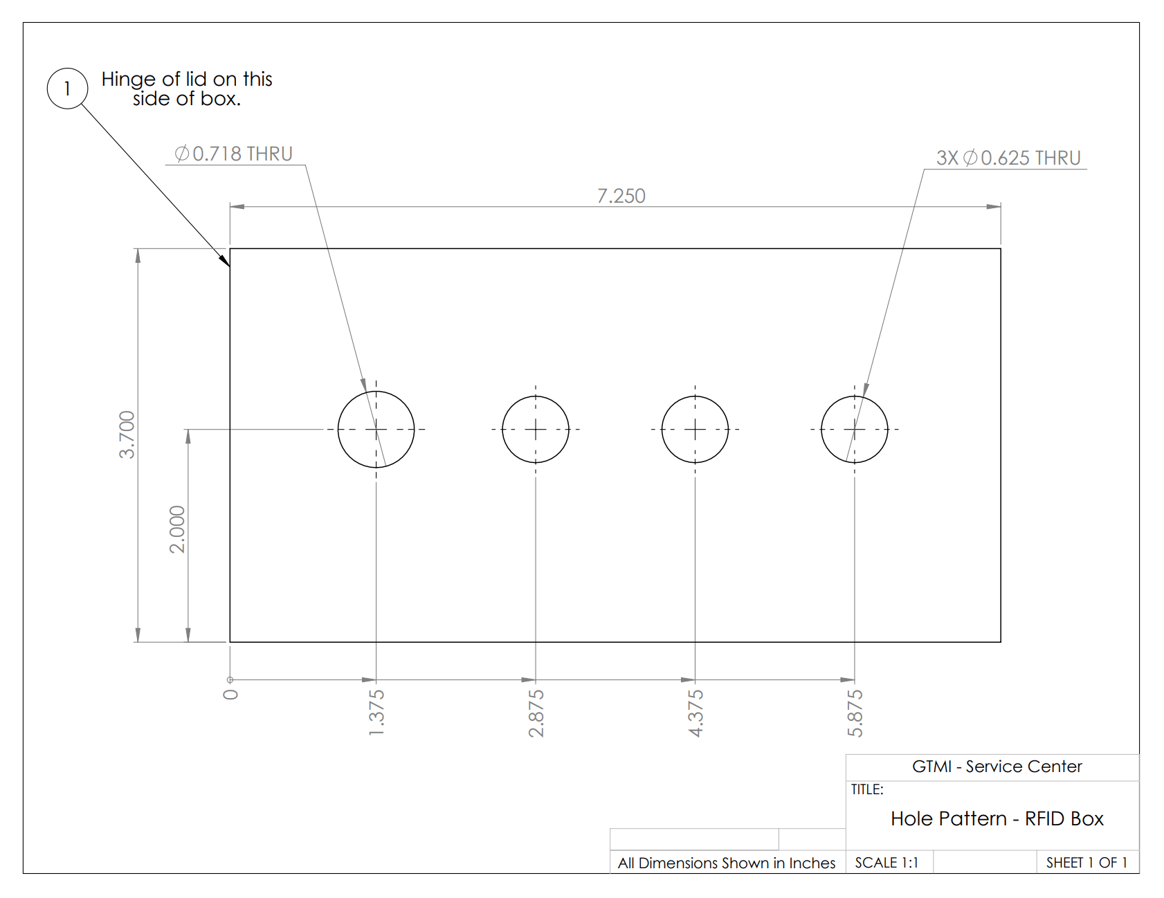
Figure 1. NEMA Box Modifications
Step 2. Insert connectors
You’ll need:
- (2x) M12 Connectors Female to wire
- Halex F Cable stress relief port
- PG9 Cable gland
Steps:
- Install the Halex F Cable stress relief port into the left-hand hole.
- Install the two M12 connectors go into the center 2 holes (note: the M12 connector on the left will be used for the IR sensor. the M12 connector on the right will be used for the REED switch)
- Install the PG9 Cable Gland into the right-hand hole.
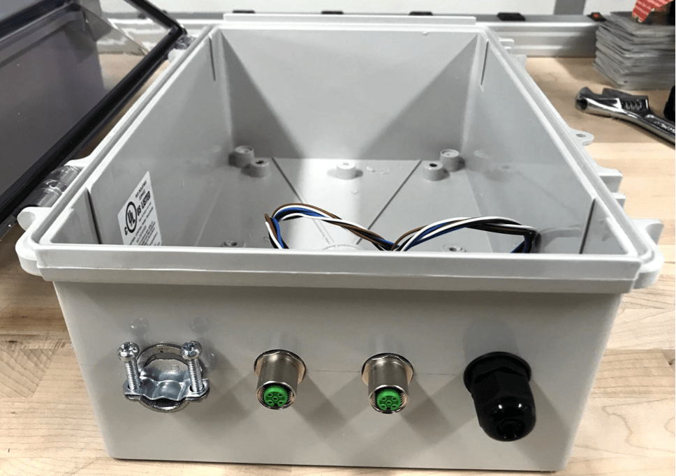
Figure 2
Step 3. Install the DIN Rail onto the DIN Rail mounting plate and install into the box
You’ll need:
- DIN Rail 9.5″ long
- (4x) M5x10 bolts
- (4x) 6-32 x 3/8″ bolts
- (4x) #6 washers
- (4x) 6-32 Nylon lock nut
- (4x) 4-40 x 3/16″ bolt
- (4x) 4-40 Nylon lock nut
- (4x) Cable tie brackets
- Blue Loctite
Steps:
- Bolt the DIN Rail down the center of the mounting plate using the 6-32 x 3/8″ bolts, the #6 washers, and the 6-32 lock nuts.
- Use the 4-40 bolts and nuts to fasten 4 cable tie brackets to the mounting plate at the smaller hole pattern on the plate
- Place a drop of Blue Loctite on the M5x10 Bolts and use them to mount the plate into the NEMA box
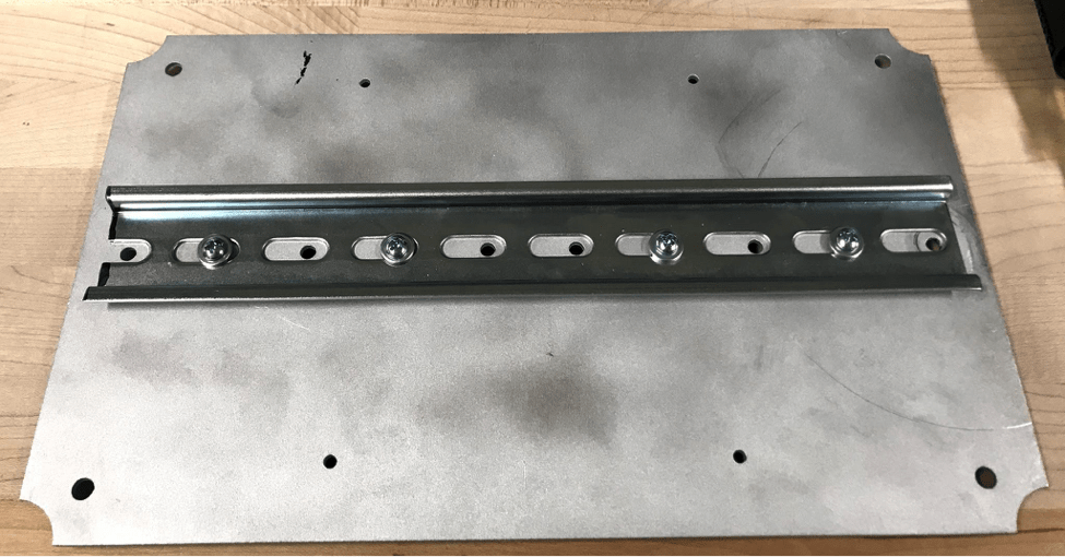
Figure 3
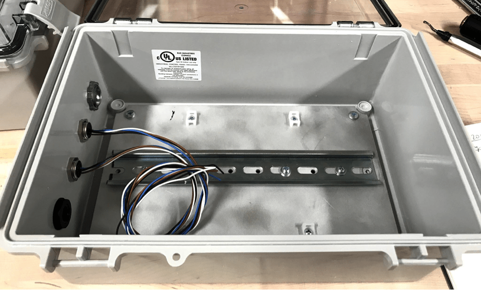
Figure 4
Step 4. Assembling the Level Shifter BBB Cape
You’ll need:
- 8-channel level shifter P395 from Adafruit
- Level Shifter BBB Cape
- (2x) 46 position BBB headers
- (2x) 10 position terminal block
- Solder Iron
- Solder
- Desoldering Wick or Desolder Pump
Steps:
- Open Adafruit bag and snip headers to length
- Put level shifter on top of headers and put the stack in holes of the cape for alignment as shown in Figure 6
- Solder the corners of the level shifter to the header pins
- Remove from the cape and solder the remaining joints
- Put the lever shifter back on top of the cape (ensure proper alignment of 3v3 and 5v) then flip over and solder legs to the bottom of the cape as shown in Figure 8.
- Put in terminal blocks (open holes facing outwards) and solder to the cape (flip upside down)
- Put in 46 pin headers and solder them to the cape
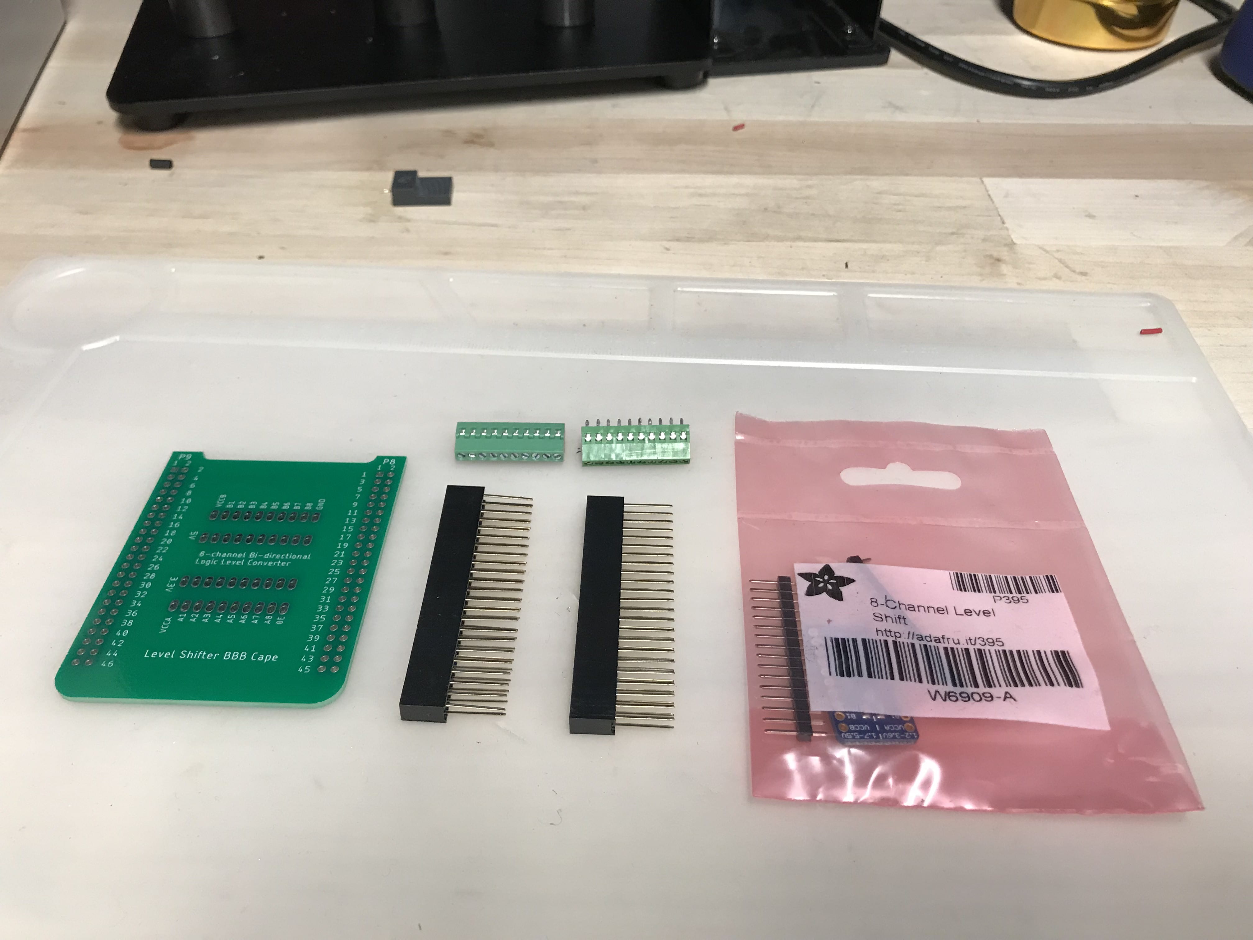
Figure 5

Figure 6
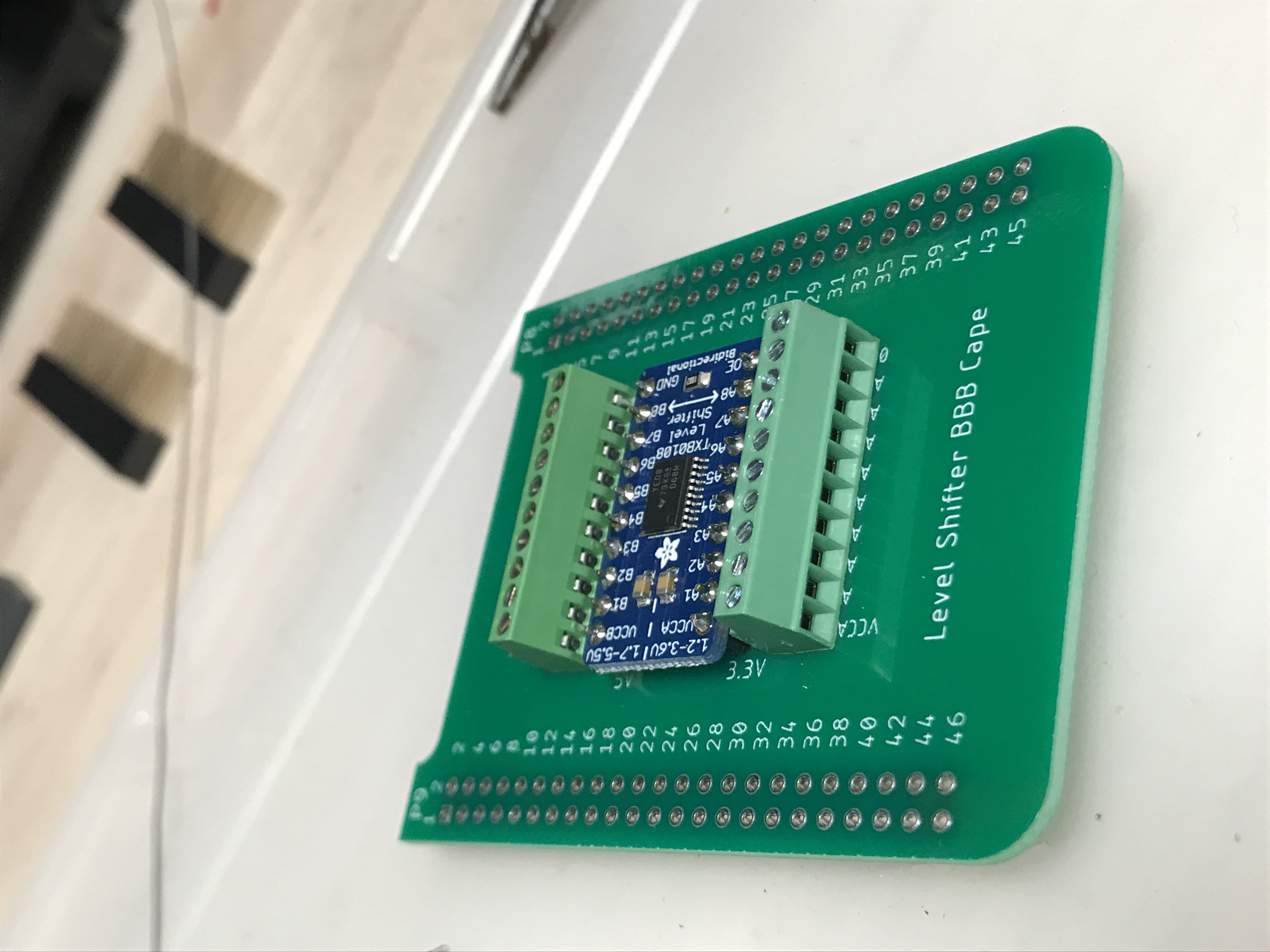
Figure 7
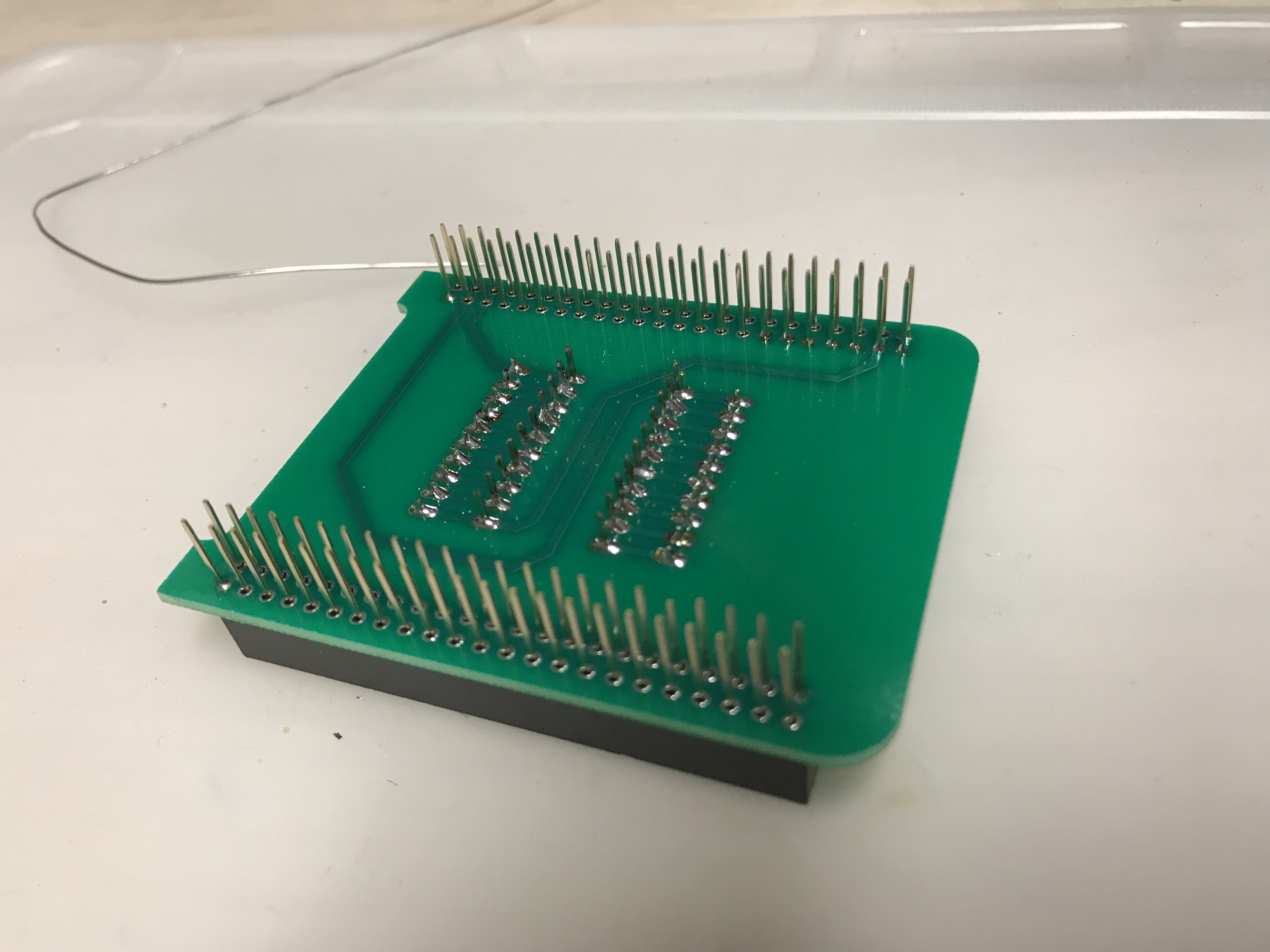
Figure 8
Step 5. Assemble the BeagleBone Black DIN Rail Adapter
You’ll need:
- BeagleBone Black Wireless PN: BBBWL-SC-562-ND
- (8x) Pan Head 4-40 x 1/4 bolt
- (4x) Round Standoff 4-40 x 3/8
- DIN rail plate for BBB
- (2x) Flathead 6-32 x 3/8 bolt
- (2x) 6-32 nut
- DIN Rail Clip, DINM13-RC
Steps:
- Assemble the BeagleBone Black to the DIN Rail adapter per Figure 9. (note: the BBB and DIN BBB adapter plate do not have symmetric hole locations and must be rotated correctly to assemble.)
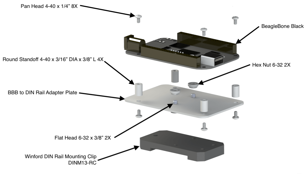
Figure 9. BeagleBone Black DIN Rail Adapter Assembly
Step 6. Assemble the RFID Board DIN Rail Adapter
You’ll need
- (8x) Pan Head 4-40 x 1/4 bolt
- (4x) Round Standoff 4-40 x 3/8
- DIN rail plate for RFID Board
- (2x) Flathead 6-32 x 3/8 bolt
- (2x) 6-32 nut
- DIN Rail Clip, DINM13-RC
- 12 position terminal block
- Soldering Iron
- Solder
- Solder flux
Steps:
- Solder the 12 position terminal block to the top of the RFID Board as shown in Figure 10
- Assemble the RFID Board to the DIN Rail Adapter in a very similar fashion as BBB. Refer to Figure 10 for completed pictures
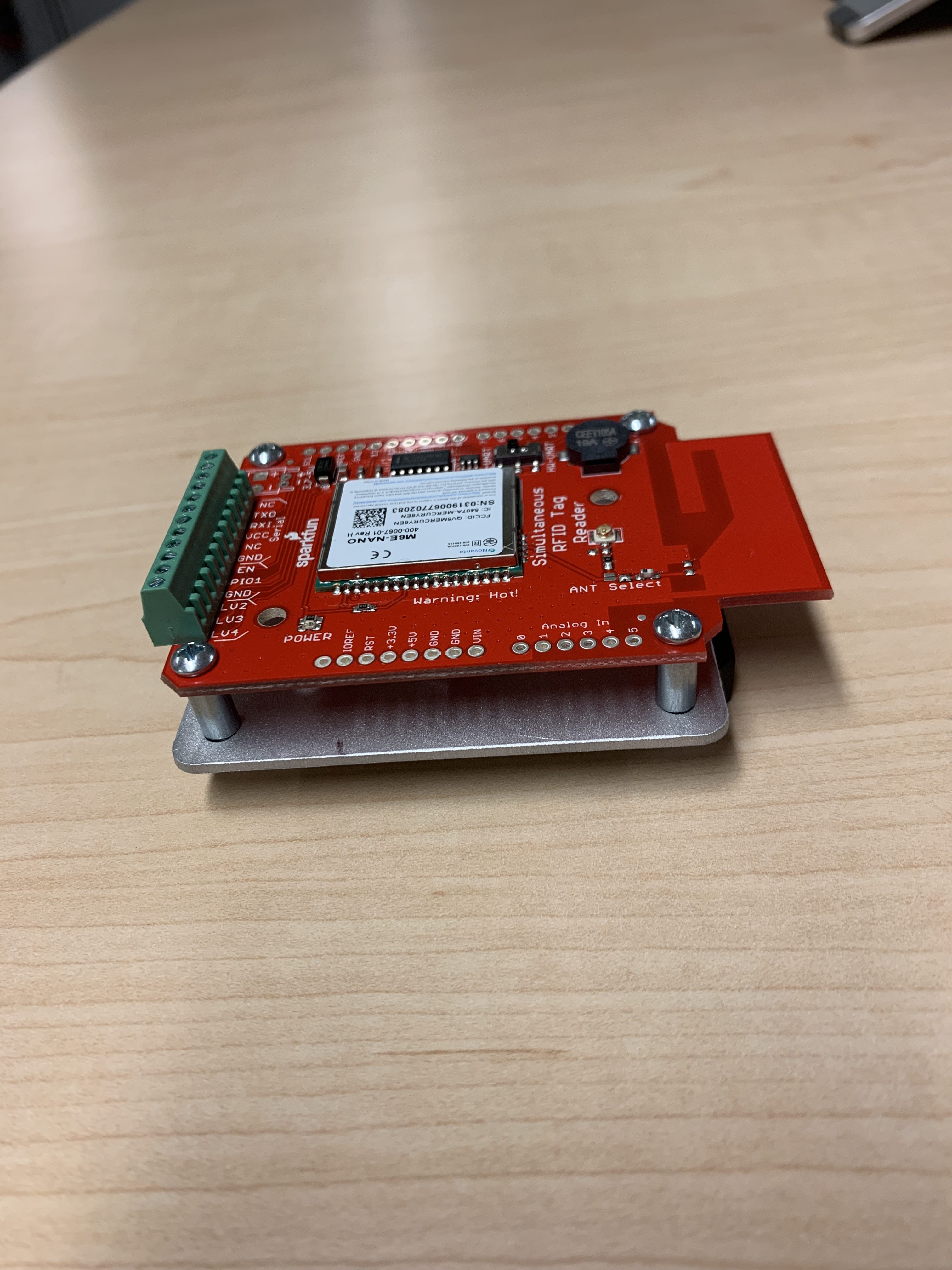
Figure 10
Step 7. Attach all items to the DIN Rail
You’ll need:
- 5V Power Supply
- 24V Power Supply
- (x2) 24V Relays
- BBB
- RFID sensor
Steps:
- Attach the Level Shifter Cape to the BBB
- Attach the items to the DIN Rail in the order shown in Figure 11.
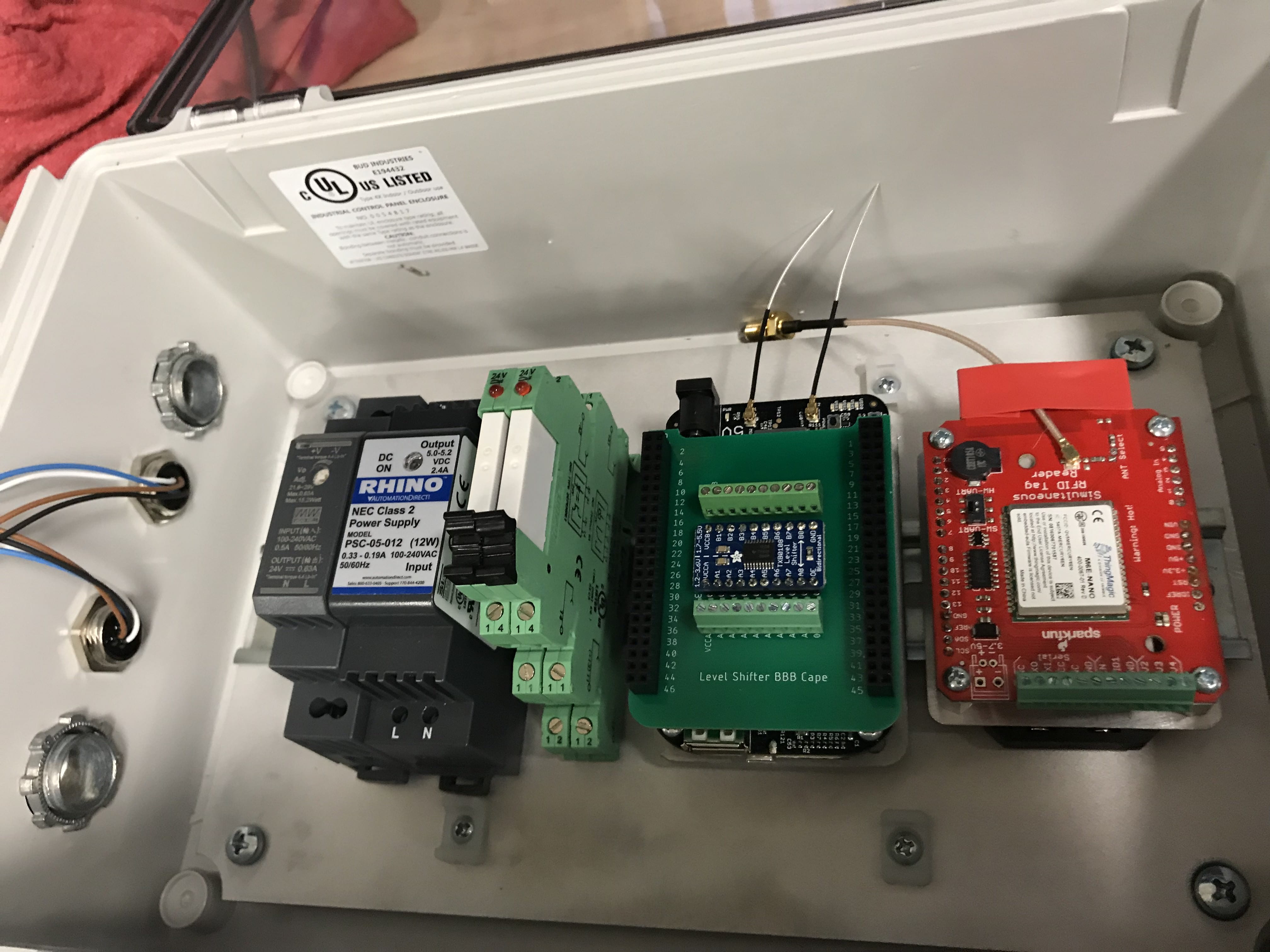
Figure 11
Step 8. Wire the RFID Board to the Level Shifter Cape and then to the Proto Cape
You’ll need:
- (3x) 22 AWG – 1’ in length – Brown, Blue, & Yellow
- (3x) 22 AWG – 6″ in length – Brown, Blue, & Yellow
- Proto Cape kit for BBB. PN: 1528-1364-ND
Steps:
- Use the longer wires to connect the RFID Board to the Level Shifter as shown in Figure 12
- Use the shorter wires to connect the Level Shifter to the Proto Cape as shown in Figure 13
- Reference Table 1 for wiring connections
| Connection | Brown | Blue | Yellow |
|---|---|---|---|
| RFID to Level Shifter | TXO > B1 | RX1 > B2 | EN > B3 |
| Level Shifter to Proto Cape | A1 > P9_26 | A2 > P9_24 | A3 > P9_27 |
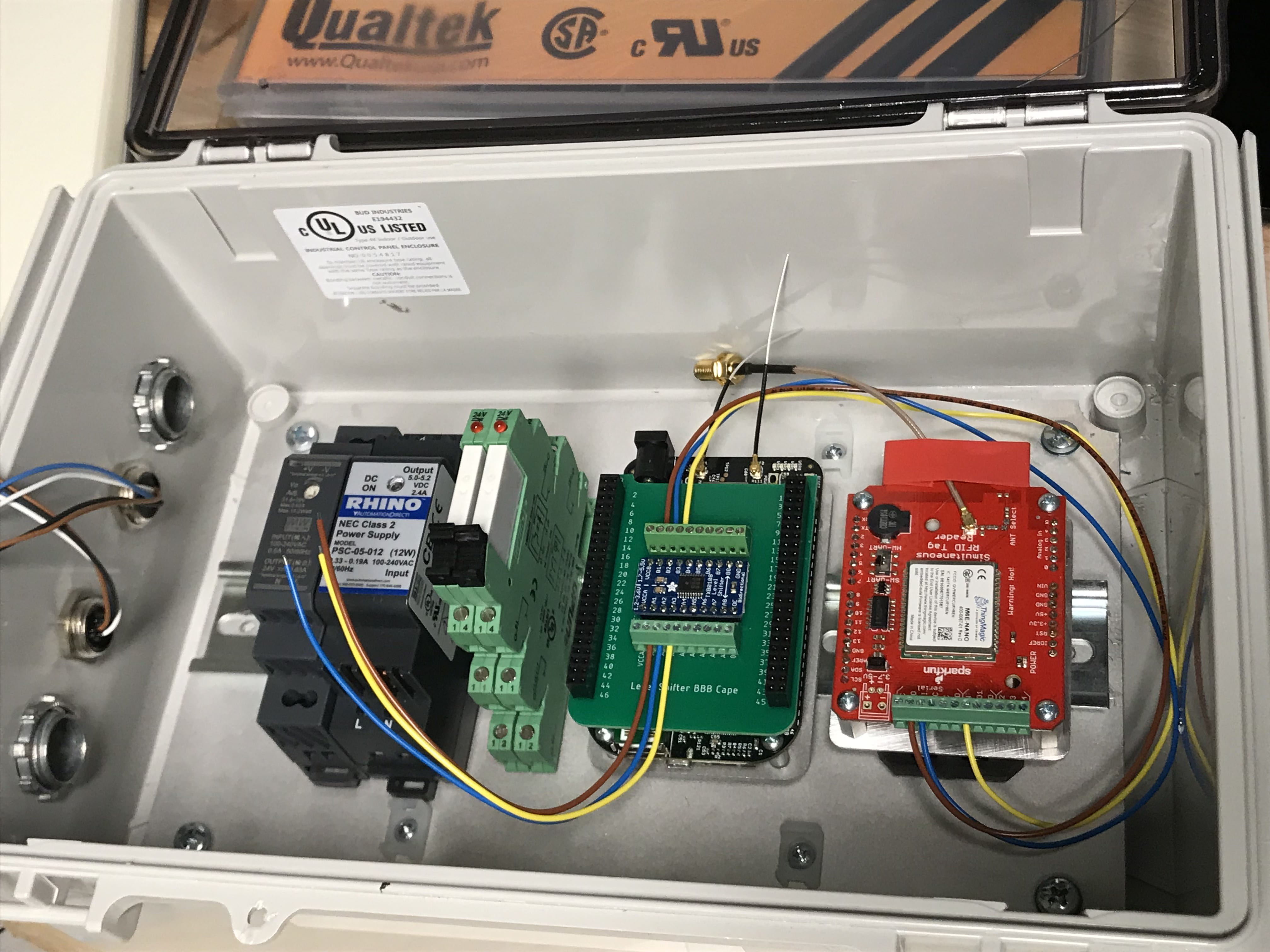
Figure 12
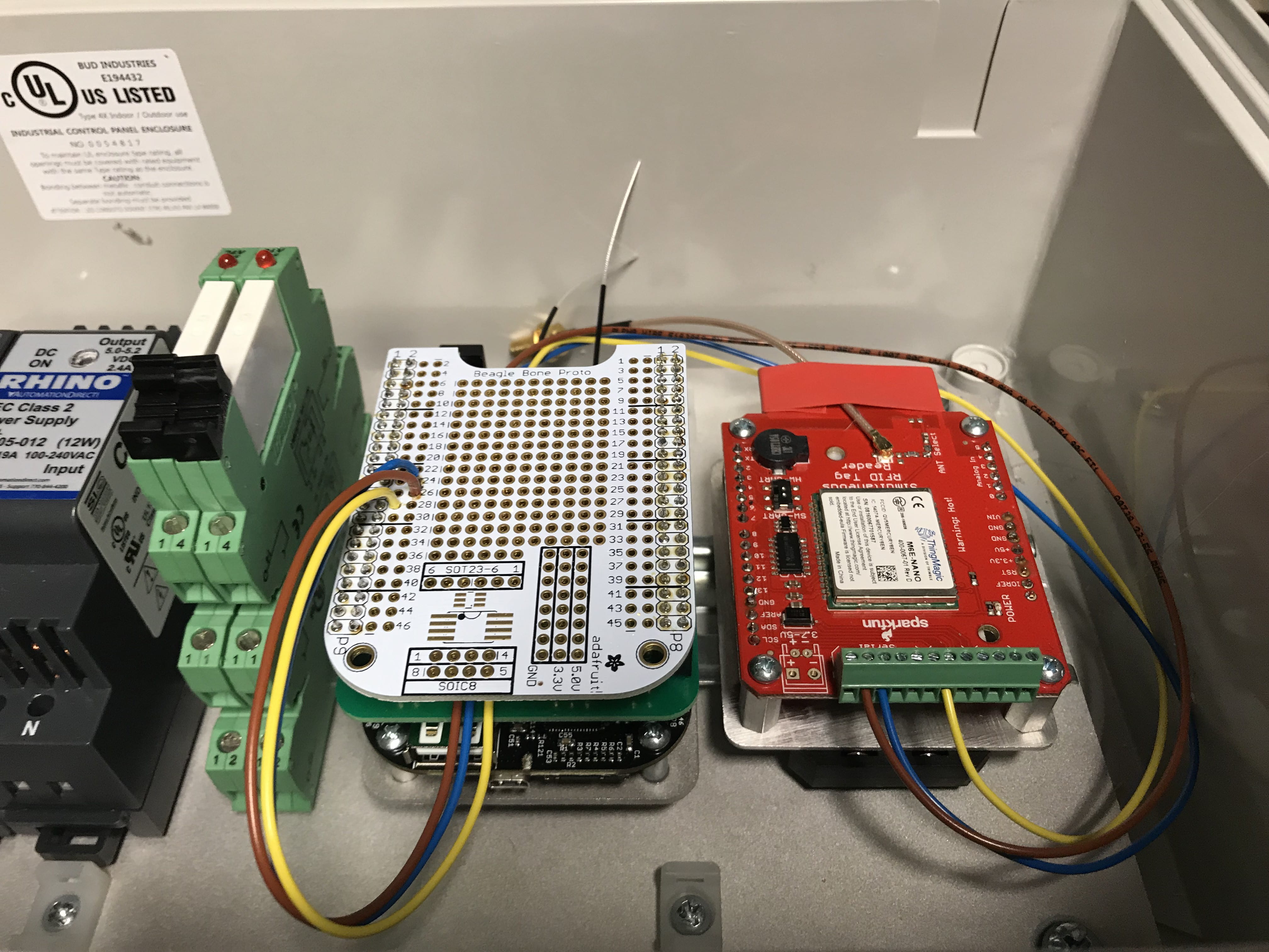
Figure 13
Step 9. Wiring the 5V Power Supply to the BBB and RFID Board
You’ll need:
- 5V Power Cable for the BBB. PN: 172-4204-ND
- Blue 22 AWG wire – 16” in length with exposed ends
- Brown 22 AWG wire – 16” in length with exposed ends
- Soldering Iron
- Solder
Steps:
- Trim the 5v Power Connector to approximate 5″ in length and strip .25″ of the wire
- Solder one end of the Brown wire to the positive wire (dotted line on the wire) of the power connector as shown in Figure 14
- Solder one end of the Blue wire to the negative wire of the power connector as shown in Figure 14
- Place the Brown and positive soldered together connection in the positive terminal of the power supply
- Place the Blue and negative soldered together connection in the negative terminal of the power supply
- The remaining end of the Brown wire is to be attached to the VCC terminal of the screw terminal on the RFID board
- The remaining end of the Blue wire is to be attached to the GND terminal of the screw terminal on the RFID board
- The barrel connector on the 5V power cabled plugs into the BBB
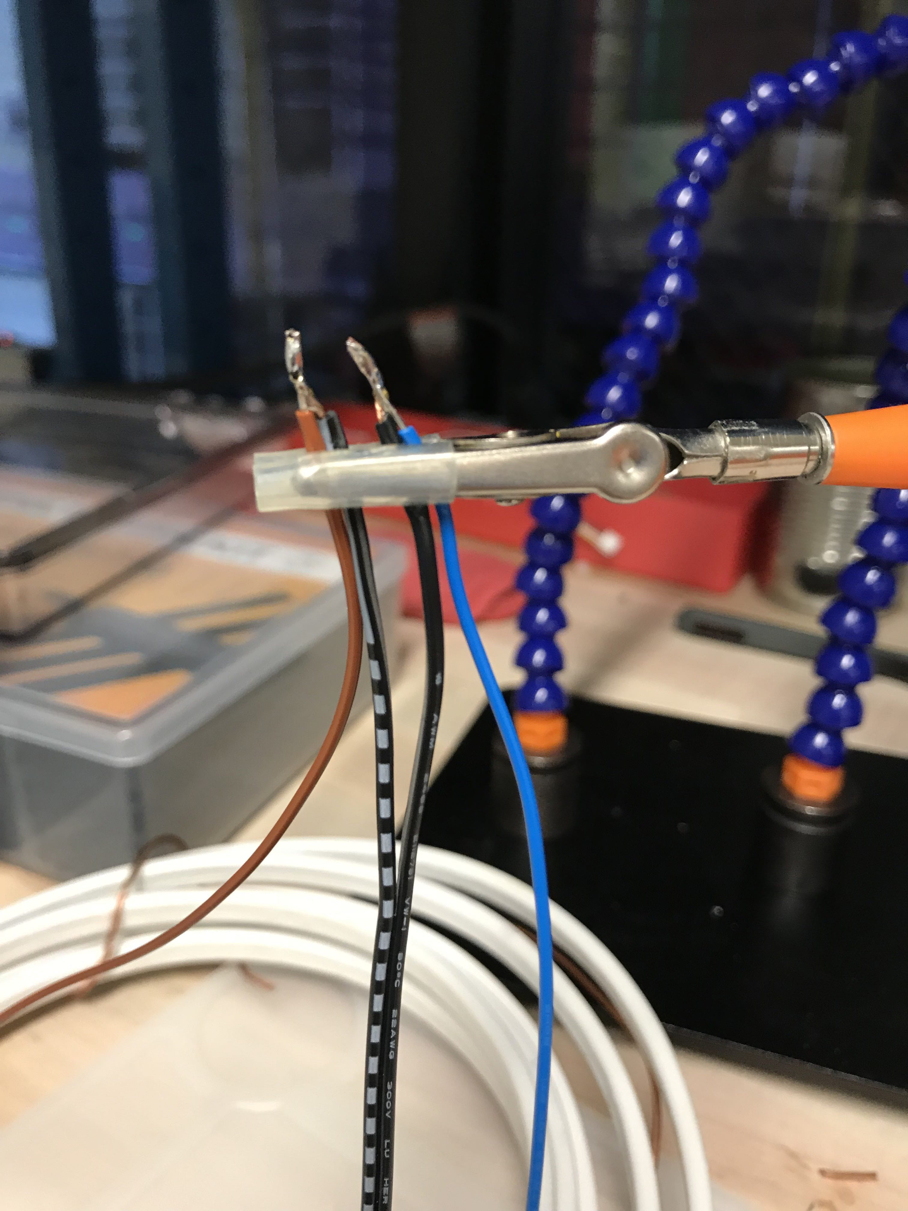
Figure 14
Step 10. Wiring the Sensor Inputs
You’ll need:
- (2x) White 22 AWG wire – 4″ in length
- 18 gauge copper wire – unsheathed and 1/2″ in length
- Solder Iron
- Solder
- Wire Snips
- Heat Shrink – 1″ in length
Steps:
- Solder both brown sensor wires (extended from M12 Connectors) to a 4” section of white wire
- Then solder those to the unsheathed copper wire ~18 AWG solid core as shown in Figure 15
- Place the heat shrink over the connection leaving only 3/8″ of the sold 18 AWG wire exposed and heat to seal
- Insert the exposed solid wire into the Positive terminal of the 24V power supply
- The tail end of the 4″ white wire (from the previous step) is be connected the IR Sensor Relay A1
- The white wire from the IR sensor M12 connector connects to the IR Relay A2
- Take the blue wire from the IR Sensor and solder it the unused 4″ section of white wire and place the soldered connection into the negative terminal of the 24V power supply
- The tail end of the 4″ white wire (from the previous step) is be connected the Reed Switch Relay A2
- The white wire from the Reed Sensor M12 connector connects to the Reed Switch Relay A1
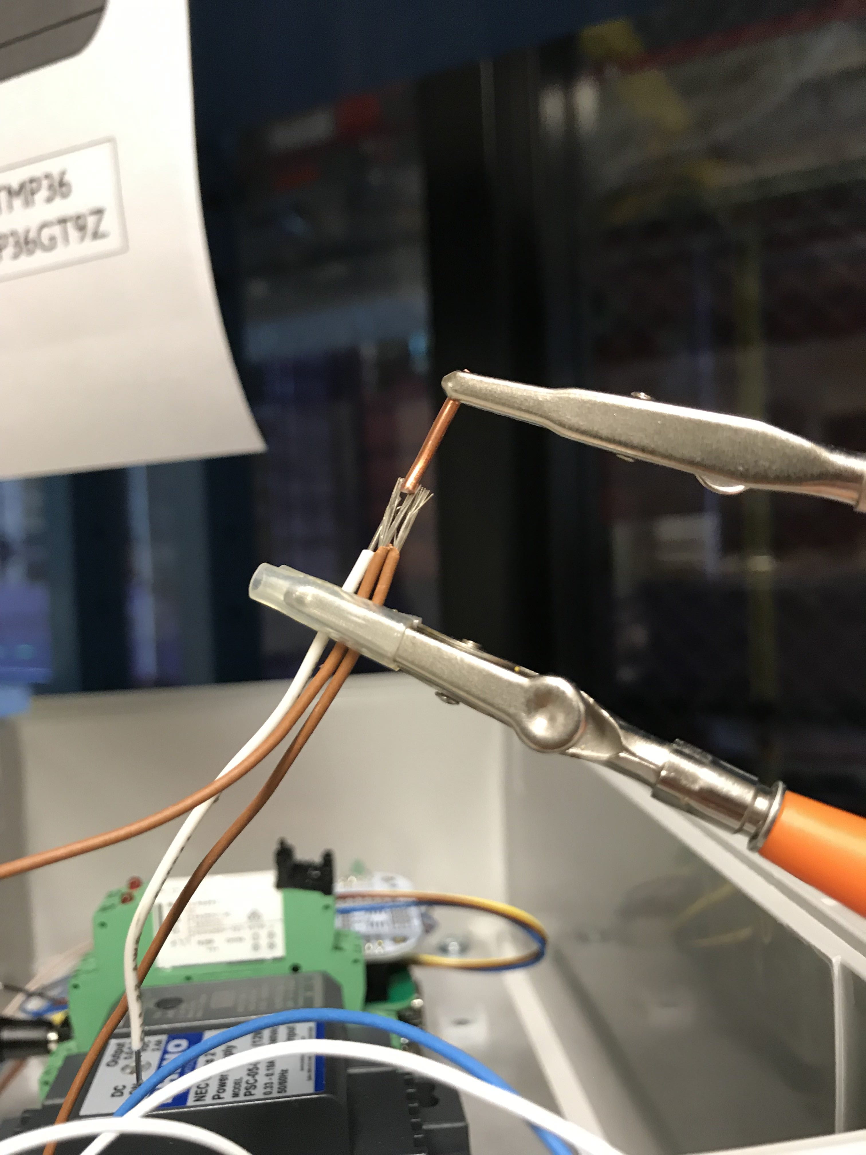
Figure 15
Step 11. Wire the Relay’s to the Proto Cape
You’ll need:
- (4x) Green 22 AWG wire – 6″ in length
Steps:
- Using a Green wire, connect Reed Switch Relay terminal 14 to the P9_14 on the Proto Cape
- Using a Green wire, connect IR Sensor Relay terminal 14 to the P9_16 on the Proto Cape
- Using the last 2 Green wires, connect terminal 11 on each relay to 3v3 on Proto Cape
- Reference the Wiring Diagram in Figure 16
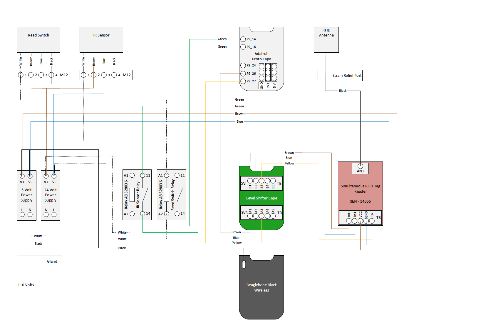
Figure 16
Step 12. Wire the 120V AC to the Power Supplies
You’ll need:
- (x2) White 18 AWG wire 5” in length
- (x2) Black 18 AWG wire 5” in length
- Power Cord. PN: 42-1009-ND
- (x2) 3 Position union
Steps:
- Insert the pigtails of the power cord through the PG9 Cable Gland
- Connect the White wire from the power cord to both white wires in a 3 position union
- White wires go into N on each power supply
- Connect the Black wire from the power cord to both black wires in another 3 position union
- Black wires go into L on each power supply