
Note: This page assumes that the components of the physical sensor box (including the DIN rail mount, 120V-5V power converter, and M8 connectors) have already been installed.
1. Construct the current sensors:
- Cut the 1/8″ connector off of the end of the current sensor cable.
- Strip back the sheath and trim the excess shielding wire to expose approximately 1.5″ of the red and white wire ends.
- Strip approximately 1/4″ off of the red and white wire jackets.
- Take the M8 cable and strip back approximately 1.5″ of the sheath to expose the white, black, brown, and blue wire ends.
- Trim the excess shielding wire and cut the black and blue wire ends off, leaving only the white and brown wire ends.
- Strip approximately 1/4″ off of the brown and white wire jackets.
- Cut one piece of appropriately sized heat shrink and fit it over the M8 cable. Cut two appropriately sized pieces of heat shrink and fit them either over the white and red ends of the current sensor cable or the white and brown ends of the M8 cable. Make sure to place the heat shrink as far away from the exposed wire ends as possible. Place the heat shrink on BEFORE completing the next step.
- Twist the ends of both the white and red ends of the current sensor cable and the white and brown ends of the M8 cable. Apply flux to each wire end, then fold each end into a hook shape and attach wire ends together in the following manner: white end of the current sensor cable to white end of the M8 cable and red end of the current sensor cable to the brown end of the M8 cable.
- Solder the connected wire ends together. Then slide the two pieces of heat shrink over the soldered wire ends and use the heat gun to collapse the heat shrink.
- Slide the larger piece of heat shrink over both of the soldered wires. Make sure that some of the heat shrink is also covering a portion of the current sensor cable and the M8 cable. Use the heat gun to collapse the heat shrink.
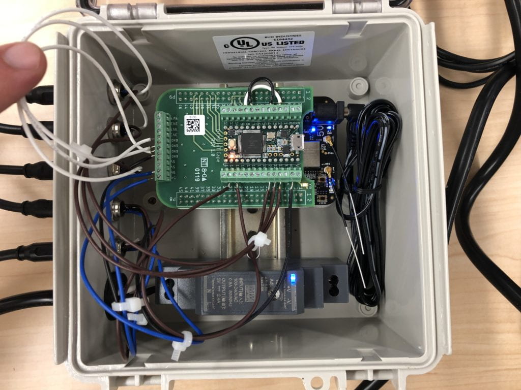
Figure 1. Multi-sensor kit viewed from the top.
2. Construct the temperature sensor:
- Take the M8 cable and strip back approximately 1.5″ of the sheath to expose the white, black, brown, and blue wire ends.
- Trim the excess shielding wire and cut off the white wire end.
- Strip 1/4″ off the blue, brown, and black wire jackets. Cut an appropriately sized piece of heat shrink and place it over the M8 cable.
- Using the Temperature Sensor Analog Reference, solder the appropriate M8 connections to their respective pins on the temperature sensor. Make sure to apply heat shrink over the soldered connections to prevent a short.
- Slide the heat shrink back over the three soldered connections and use the heat gun to collapse the heat shrink.
3. Construct the accelerometer:
- Take the ADXL203EB accelerometer and remove the header pins.
- Take the M8 cable and strip back approximately 1.5″ of the sheath to expose the white, black, brown, and blue wire ends.
- Trim the excess shielding wire and strip 1/4″ off the blue, brown, white, and black wire jackets.
- Take one of the black accelerometer boxes out of the plastic bag, fix it in the bench vise and use a 7/32″ drill bit to make a hole in the approximate center of the side of the box.
- Run the M8 cable through the hole in the box BEFORE proceeding to the next step.
- Twist the wire ends of the M8 cable and apply flux.
-
Solder the stripped wire ends of the M8 cable into the accelerometer pin holes in the following manner:
M8 Accelerometer White GND Blue V+ Brown (X or Y) Black (X or Y) - Use 4-40 flathead bolts and nylon lock nuts to attach the accelerometer to the black accelerometer box. Use the 4 pre-drilled holes in the box to put the bolts through.
- Take two cable ties and cinch one around the M8 cable on the outside of the box and one around the M8 cable on the inside of the box. Make sure that the cable ties are cinched on the M8 cable so that the tie is up against the wall of the accelerometer box.
- Use the two screws provided in the plastic bag of the accelerometer box to attach the lid to the box.
4. Connect the M8 connectors of the M8 cable for each sensor to the M8 connectors on the sensor box.