
Mechanical Assembly of Multisensor Kits
Task 1. Modify the Plastic NEMA Box
You’ll need:
- NEMA Box ABS, Digikey Part Number: 377-1787-ND
- Cordless drill
- 23/64″ hole saw
- 21/32″ hole saw
- Ruler
- Pen
- Deburr tool
Steps:
- Mark the centers of each hole using the ruler and pen per Figure 1 (hole locations within 1/8th inch are acceptable).
- Drill the holes using the hole saws.
- Deburr the holes to ensure a clean fit.
Figure 1. Modifications to NEMA Box.
Task 2. Bolt the DIN Rail into the box
You’ll need:
- Blue Loctite
- (2x) Pan Head M4x6mm
- DIN Rail. PN: 277-2064-ND
Steps:
-
- Cut down the DIN Rail to approximately 130mm (comes in 1000mm sections from supplier)
- Place a drop of Loctite on the threads of the M4 bolts
- Screw the DIN rail into the threaded holes parallel to the M8 Connectors and Cable Gland
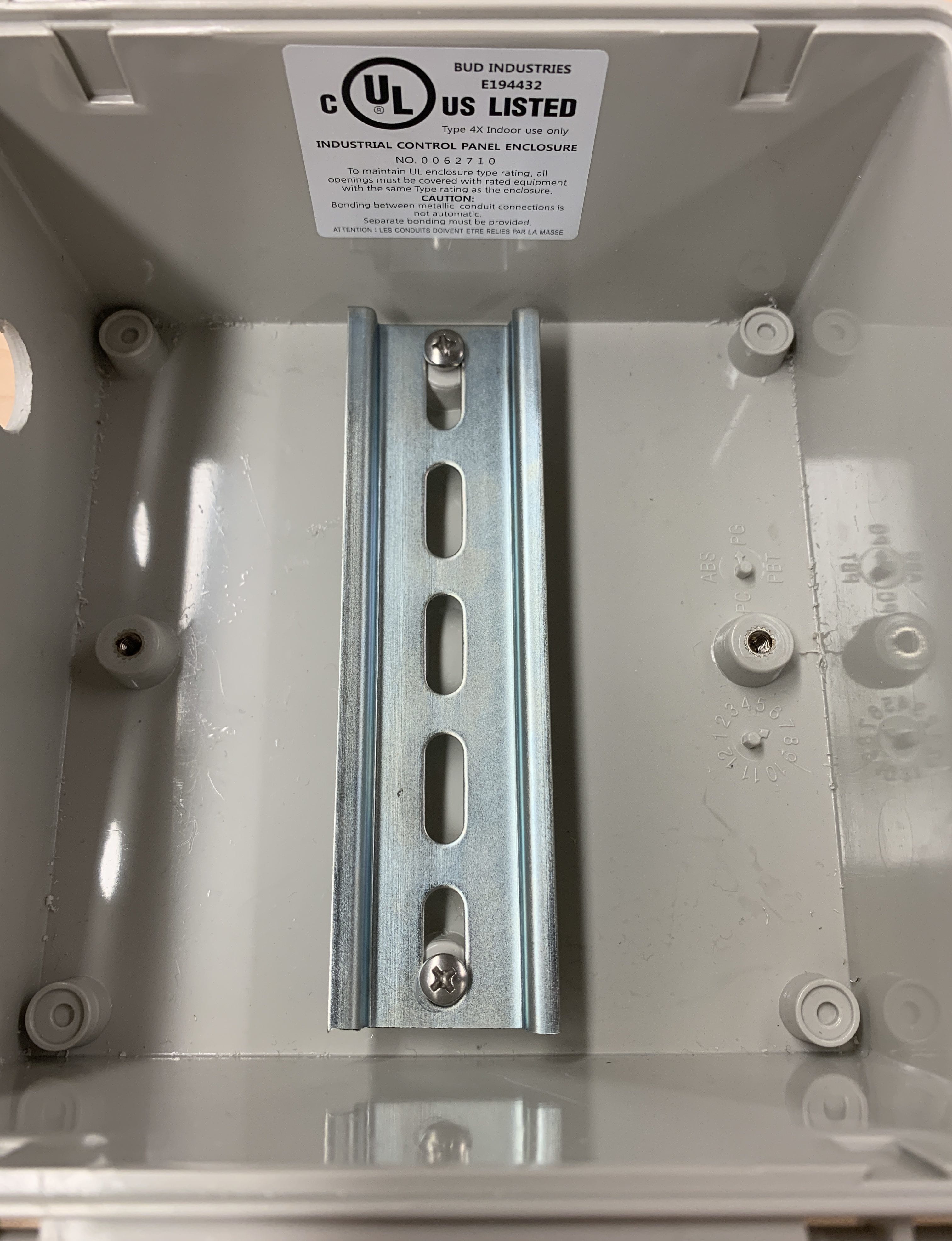
Figure 2. DIN Rail Installation
Task 3. Insert the M8 Female-to-wire connectors and Cable Gland
You’ll need:
- (5x) M8 Bulkhead Connector, female to wire. PN: A126830-ND
- Cable Gland PG9. PN: 377-1631-ND
Steps:
- Unscrew the nut on the M8 connector, insert them from the inside and torque the nut on the outside. Repeat with the other 4 holes.
- The cable gland is assembled similarly in the last and largest hole cut out.
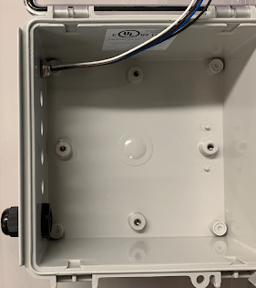
Figure 3. M8 connector and Cable Gland Install
Task 4. Assemble the Beagle Bone Black to its DIN Rail Adapter
You’ll need:
- BeagleBone Black Wireless PN: BBBWL-SC-562-ND
- (8x) Pan Head 4-40 x 1/4 bolt
- (4x) Round Standoff 4-40 x 3/8
- DIN rail plate for BBB
- (2x) Flathead 6-32 x 3/8 bolt
- (2x) 6-32 nut
- DIN Rail Clip, DINM13-RC
Steps:
- Assemble the BeagleBone Black to the DIN Rail adapter per Figure 4. (note: the BBB and DIN BBB adapter plate do not have symmetric hole locations and must be rotated correctly to assemble.)
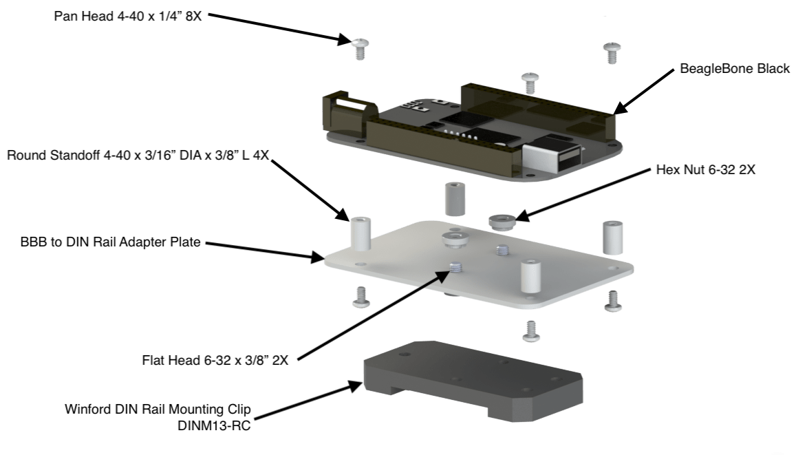
Figure 4. BeagleBone Black DIN Rail Adapter Assembly
Task 5. Solder the Teensy to the Cape and attach the Cape onto the top of the BeagleBone Black
You’ll need:
- Teensy 3.2 K20 EVAL BRD. PN: 1528-2385-ND
- BBB Teensy Cape
- BeagleBone Black on DIN Rail Adapter from step 4
- Solder Iron
- Solder
- Solder Flux
- Solder wick or Desoldering pump
Steps:
- Solder the Teensy board to the BBB Teensy Cape
- Attach the Cape to the top BeagleBone Black by aligning the pin connector
Figure 5. Teensy Soldered to Cape and installed onto BeagleBone Black
Task 6. Affix the BeagleBone Black Assembly and Power Adapter into the Box
You’ll need:
- BeagleBone Black Assembly from step 5
- Nema Box with Connectors and DIN Rail installed from Step 3
- AC/DC Converter 5v 12W. PN: 1866-2241-ND
Steps:
- Attach the BeagleBone Black Assembly to the DIN Rail as shown in Figure 6
- Attach the AC/DC Converter to the DIN Rail as shown in Figure 6
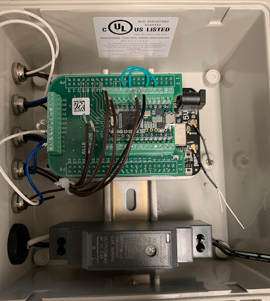
Figure 6. Power Converter and BeagleBone Black installed onto DIN Rail
Electrical Wiring
Task 1. Wire the box
You’ll need:
- The assembled box from step 6
- Cable Assy R/A 2.1mm 6′ 24 AWG. PN: CP-2189-ND
- Cord 16AWG Nema 1-15P to CBL 4.92′. PN: 42-1009-ND
Steps:
- Insert the power cord through the Cable Gland as shown in Figure 6 and wire into the converter
- Wire the M8 Connector wires to the BeagleBone Black Assembly as shown in Figure 7
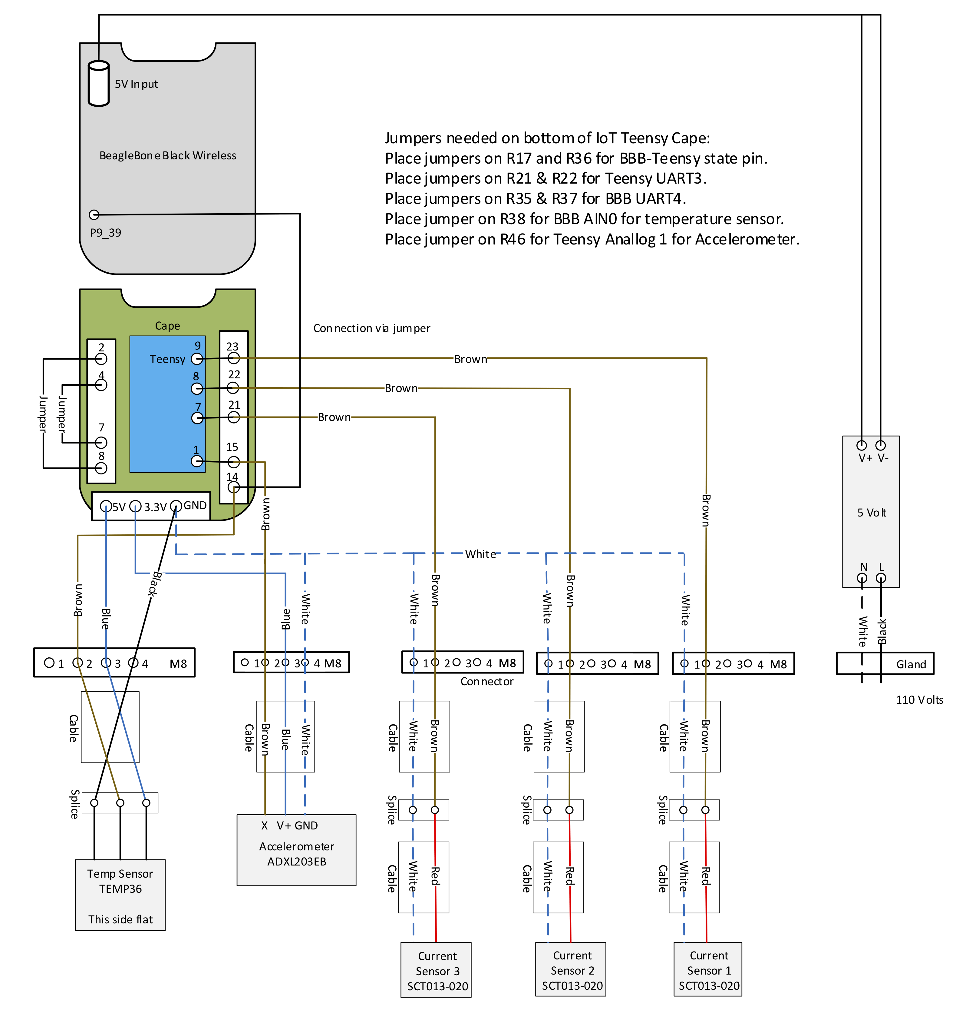
Figure 7 (wiring diagram)
Sensor Assembly
Task 1. Assemble 3 current sensors
You’ll need:
- (3x) M8 Male to Wire. PN: A120882-ND
- (3x) Current Sensor. PN: 1597-1312-ND
- (6x) Smaller Cable Heat Shrink Sleeve approximately 1″ length
- (3x) Larger Cable Heat Shrink Sleeve full length
- Wire strippers and cutters
Steps:
- Snip off the 3.5mm Audio Jack from the Current sensor and strip the cable 1.5″ exposing the 2 smaller wires. Then strip the individual wires approximately .25″ to expose to copper wire.
- Expose the wires in the M8 connector by stripping the cabled 1.5″ and stripping individual wires .25″
- Hook the wires of the current sensor to the M8 connector referencing Table 1
- Place the heat shrinks over the wires as shown in Figure 8 (place all heat shrinks on before soldering)
- Solder the wires together
- Use the smaller heat shrinks to cover the connected wires
- Unused wires may be clipped
- Use the larger full length heat shrink to enclose the entire splice area
- Repeat steps 1-8 three times to make 3 current sensors
| Current Sensor | M8 Connector |
|---|---|
| Red | Brown |
| White | White |
Table 1

Figure 8
Task 2. Assemble the Temperature Sensor
(Note: there are two different Temperature sensors. You will need to know if you will be using the analog pin-type sensor or the waterproof cable sensor before continuing)
You’ll need:
- Temp Sensor Analog. PN: TMP36GT9Z-ND or Temp Sensor Waterproof. PN: DS18B20
- M8 Male to Wire. PN: A120882-ND
- (3x) Smaller Cable Heat Shrink Sleeve, approximately 1″ length
- Larger Cable Heat Shrink Sleeve, full length
- Wire strippers and cutters
Steps for analog pin-type temperature sensor :
- Expose the wires of the M8 connector and place the heat shrinks on the wires as shown in Figure 9
- Follow the Analog Temp Sensor Reference Solder the wires to the correct pins
- Heat shrink the soldered connections
- Unused wires can be clipped
- Place the larger heat shrink over the entire connection leaving on the tip of the temperature sensor exposed
Figure 9
Steps for waterproof cable type temperature sensor:
- Strip both the temperature sensor wires and M8 connector wires
- Place the heat shrinks over the wires
- Solder the wires together according to Table 2
- Unused wires may be clipped
- Heat shrink the individual connections together
- Heat shrink the entire splice together
| Temperature Sensor | M8 Connector |
|---|---|
| Black | Black |
| White | Brown |
| Red | Blue |
Table 2
Figure 10
Task 3. Assemble the Accelerometer
You’ll need:
- Accelerometer, BOARD EVAL FOR ADXL203. PN: ADXL203EB-ND
- M8 Male to Wire. PN: A120882-ND
- Accelerometer box PN: 1551RBK
- (3x) Smaller Cable Heat Shrink Sleeve, approximately 1″ length
- Drill and 7/32″ Bit
- (2x) 4-40 x 3/8″ Flat Head bolts
- (2x) 4-40 Nylon lock nut
- (2x) Cable Ties
Steps:
- Drill a 7/32″ hole into the center of one of the sidewalls of the Black Accelerometer Box
- Clip the corners of the pin mount on the accelerometer board to allow for clearance of the mounting nut.
- Use the bolts and nuts to attach the accelerometer to the Black Accelerometer Box.
- Use the wire strippers to expose the wires of the M8 cable
- Insert the M8 Cable into the hole in the box and place the heat shrinks on the wires.
- Solder the cables to the pin of the accelerometer according to Table 3
- Unused pins and wires may be removed
- Place the heat shrinks over the wires and pin connections to insulate them
- Use the cable ties on the M8 cable just before and after the hole in the box to secure the cable
| M8 Connector | Accelerometer |
|---|---|
| White | Ground |
| Brown | X |
| Blue | V+ |
Table 3
Figure 11